Aug 2021 - Mar 2022
ROLE
Computer-aided engineering (CAE) engineer
DIVISION
Simulation, Technology Research
TEAM
CAE
Product design
System design
Reliability
Marketing
IT
Goal
The aim is to lead the IT section of the simulation team (CFD + FEA)*, from managing servers, connectivity to storage. Concurrently, research on AI integration for process automation, and execution of CFD simulations to optimize efficiency and costs for the product and reliablity (testing) teams were of top priority.
*FEA = Finite Element Analysis; CFD = Computational Fluid Dynamics. Both are subsets of CAE (Computer-Aided Engineering).
Key responsibilities
IT Infrastructure
Improve the IT infrastructure of the simulation team, from servers, connectivity, queue monitoring system to storages.
AI Research
Evaluate the feasibility of integrating AI into simulations to automate tasks, simplify processes, and enhance predictions.
CFD Simulation
Assist product designers and reliability engineers in enhancing efficiency and reducing costs through time-saving simulations and predictions.
Product coverage
Featured below is a curated collection of products and tools, spanning both software and hardware integral to the role. They enable the investigations, ideation, testing and execution of the goals.


Research
Understanding pain points, motivations, success factors and potential improvements for a specific app, feature or service.
Research methodologies
Numerous methods were utilized, with the main approaches outlined below:
Interviews
Frequent discussions between simulation, product, system design and reliability teams aim to understand the pain points and motivations from the user and business perspectives. These sessions guide both new and existing product developments.
Ensuring clarity across teams to effectively address user problems.

“Running ‘geometry cleanup’ simulations are very tedious and manual. Smart AI automation would save us time.”
CFD Engineer
“I could use more server space for running multiple simulations at once. It would speed things up big time.”
FEA Engineer
“The outdoor compressor grille needs to be more compact due to the climate conditions of the country.”
Product Design Engineer
Secondary research
Commonly employed in R&D, secondary research offers valuable insights from existing data to aid in trend prediction and decision-making.
A foundational driver for kickstarting projects. Examples:
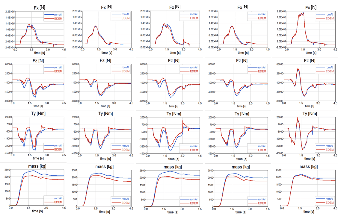
“romAI will be coupled with a wheel loader model to estimate the loads due to the bulk material interaction, significantly reducing the simulation runtime around 35 times.”

Usability testing integrates simulation and hands-on experimentation, assessing feasibility, functionality, and validation through official audit runs. These undergo iterative top-down reviews in three or four Design Reviews throughout the product development cycle. From the IT perspective, demo and pilot runs were conducted and thoroughly tested prior to official deployment.
Quality assurance and product fulfilment before market debut. Examples:
Simulation results validation with past works or physical tests
Stakeholders review and discussion
Results judgement
Official runs
Connecting the dots
While the role does not adhere to conventional UX design practices of user flow and storyboarding, their principles are integral to research and development work. Here are some relevant aspects in this domain.
Stories
The motivations behind a request or problem were unveiled with the concept of user story crafting. User needs and pain points are studied, via user journeys and user flows on the simulation processes from start to end.
STORY MOTIVATORS
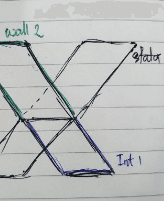
Different simulation work demands different infrastructure requirements such as RAM, number of cores, running platform and execution method.
QMS = Queue Management System
NAS = Network Attached Storage
Linux server
QMS
NAS
User journey
Research involves understanding the holistic picture of a problem.
SIMULATE THE STORYBOARD
The objective focuses on breaking down the simulation flow of the CAE team. It answers the how, why and what that affects the commissioning of the IT infrastructure.

1
Task received
Simulation work is initiated from research or R&D divisions.
2
Simulation type
Type of CAE simulation is studied, from software to requirements.
3
Scale
The size prerequisites and demand are confirmed such as input data, model size, results and renders.

4
Setup
Manual configuration and queue execution are conducted. The main motivation for automation.

5
Feedback loop
Monitoring of simulation runs, from status, progress, errors and metrics.

6
Efficient results
Simulations are completed, meeting all stakeholders' requirements and results.

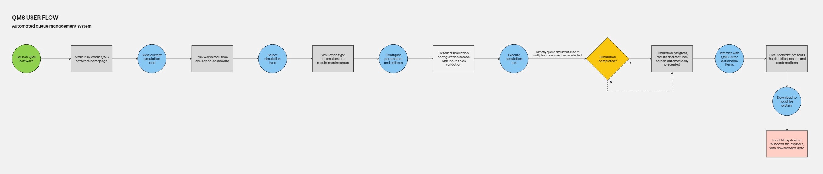
USER FLOW CRAFTING
Converting data to actionable user flow diagrams.
Ensures product alignment with user needs.
The linux-only system (above) and the QMS user flow (right) diagrams illustrate the contrast between a manually driven system versus one that leverages automations and intuitive user interfaces.
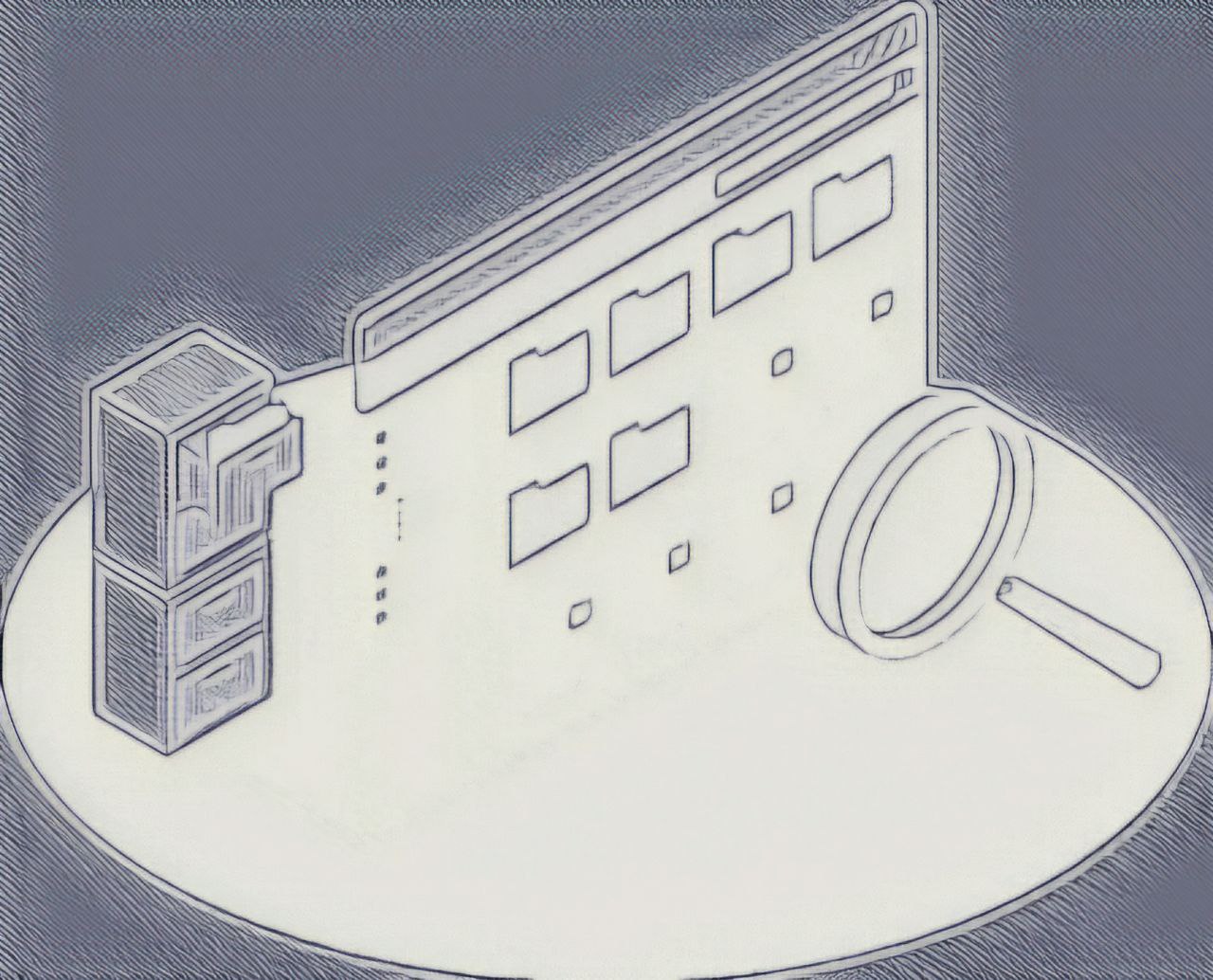
The principles of information architecture are evident in managing Linux-based systems and the creation of QMS system by Altair. The command line interface serves as the central hub for executing simulation tasks due to their extensive scale. Both systems comply to the principles of sitemaps as information would require systematic categorization to ensure scalability and optimized functionality.
LINUX FILE SYSTEM
Linux file systems operate on a hierarchical tree structure, beginning from the root directory.
A simplified example of a linux file system hierarchical structure.
With the nature of Linux single-rooted hierarchical file system, commissioning and managing servers can be complex and requires careful management. All files are under a single root directory (/) with diverse paths serving specific purposes. Misplacing files or directories can disrupt system operations.
The QMS interface is then commissioned by calling Linux directories based on simulation type, software, and statistical visualizations.
Insights
Research highlights four motivations that significantly influence the nature of a project. They may alter working methodologies, design, technical systems and project directions.
Type of simulation
Server commissioning
Simulations vary in their requirements from methodologies, demand and capacity. These factors impact the commissioning of servers, affecting aspects such as load balancing, redundancy and connectivity.
Current infrastructure
AI integration
manual
manual
manual
.csv
.csv
.csv
.sim
.sim
.sim
.vtu
.vtu
.vtu
The integration of AI into simulations is closely tied to the existing data management infrastructure. Complexity rises with highly unstructured and manually recorded data, impacting integration efforts.
IT-CAE
CFD-CAE
Geographical location
Simulation requirements

Diverse demographics across different markets demand for tailored HVAC systems, accounting for varying climate conditions, spatial allowances, and unique requirements.
Installation & Maintenance
Simulation KPIs

Understanding the user journeys related to hands-on work of HVAC units, such as the removal of front grille, is crucial. This guides the analysis of simulation results for identifying critical points.
Archetypes
These research methods facilitate the reduction of user personas into archetypes, simplifying categorization and problem definition.


Ideation
Ideation methodologies
The role covers a series of different creative thinking techniques. Below are most of the common methods:
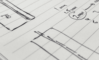
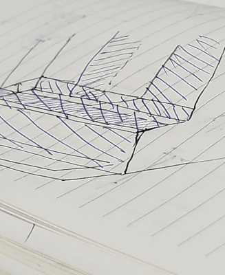
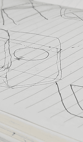
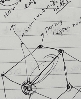
Sketches
Sketching, similar to Crazy Eights 'Rapid Sketching', is a common method used to ideate around simulation methodologies, models, or conditions. It helps visualize concepts that require high-fidelity software configurations.
Market audit
Market audit ensures meticulous market analysis and supplier selection. This method assesses gaps between possible products, potential suppliers for credibility, solution quality and cost-effectiveness.

Model study
Comparative studies often involve the analysis between simulation, experimental and reliability runs. This allows for the measurement of effectiveness of different models or setups against physical data.
How Might We?
The "How Might We?" framework is often employed to tackle key challenges and innovate solutions. In simulation engineering, there are tons of models and setup configurations available. Selecting the correct conditions is crucial for accuracy, and this method aids in refining options to address issues effectively.
- HMW -
“How might we upgrade the storage system to cater larger simulation runs?”
“How might we increase the upload and download speeds for faster results?”
“How might we streamline data collection to encourage AI integration?”
“How might we select the simulation model to attain accurate results?”
Design
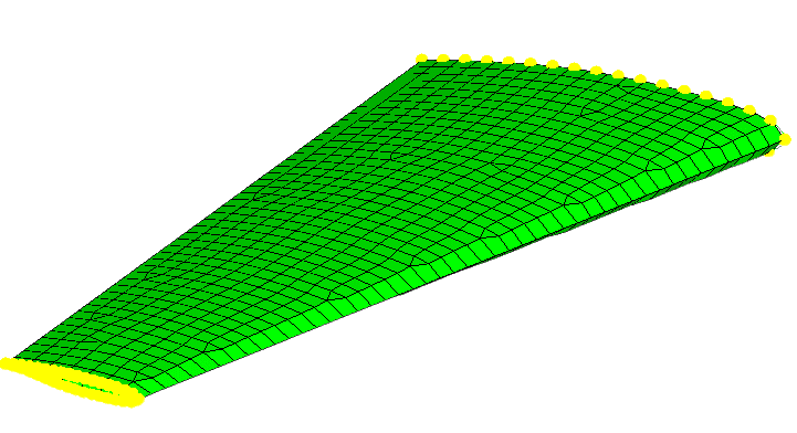
A relatable experience to wireframing and prototyping can be encountered in the Computational Fluid Dynamics (CFD) simulation process. This primarily focus on working with 3-dimensional models within industrial simulation software such as STAR-CCM+.
CFD simulation process with STAR-CCM+
After defining the problem and confirming simulation methods and conditions, the process for 3D models involves various stages: geometry cleanup, meshing, boundary conditions, solver setup, test runs, and final simulations. These stages align with UX design principles in several key functionalities.
Wireframes provide structural framework for the user experience.
Geometry cleanup & Meshing provides a computational framework for simulating fluid flow.
GEOMETRY CLEANUP
The preparation phase of the model to be simulated. Geometries or mediums are either imported, created, or modified from a past work.
The objective is to optimize the model for accurate results while reducing computational cost. Based on the flow direction, negligible sections are ‘cleaned’ (removed or simplified) and critical points are refined. Below illustrates the idea of geometry cleanup (refer this Altair tutorial on geometry for more information.)
EDIT
CLEAN
CREATE
ITERATE
GEOMETRY CLEANUP
If unstable/issues present
MESH REFINEMENT

SOLVER READY
MESHING
MESHING
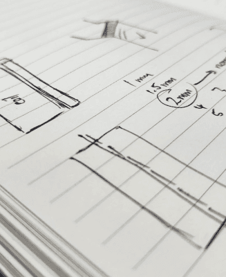
Meshing is the process of discretizing the geometry into finite elements or cells for computational analysis.
Imagine transforming a geometry into a solid body consisting of many tiny particles. This enables accurate simulation and fluid flow analysis connected throughout the geometry smoothly.
Lo-fi prototyping
Mockups
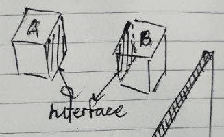
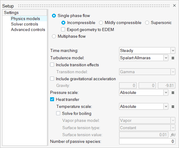
Similar to defining user interactions or limitations within an interface experience, boundary conditions and solvers define the behavior of simulated systems strategically.
BOUNDARY CONDITIONS
SOLVER SETUP
Boundary conditions of the simulation domain represents the constraints of real-world phenomenon, such as inflow and outflow locations. The solver ensures accuracy by selecting appropriate physics model for the simulation. This creates the mockup model, ready for execution.
Revisiting the issue to be addressed is crucial to ensure the flow and conditions of the simulation are accurate.
These models are referenced from Altair modeling of a heat exchanger component.
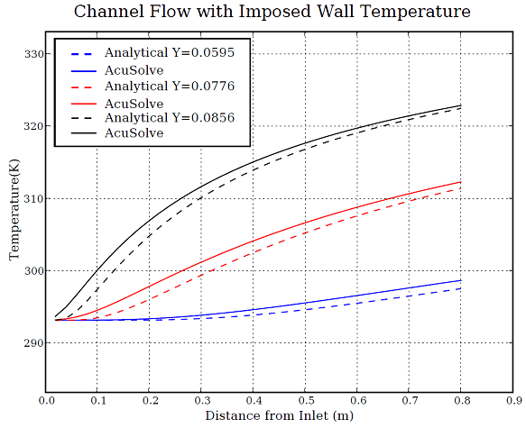
TEST RUN
Like the UX design thinking framework, this mimics the iterative process of prototyping and testing.
Examining initial hypotheses, preliminary simulations are conducted to validate the setup and identify potential issues.
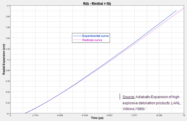
The results represent a validation test of laminar flow through a channel with heated walls by Altair, which demonstrates accuracy for higher fidelity simulations.
Hi-fi prototyping
Comprehensive simulation runs are conducted to ensure the solution is complete as a whole, similar to how hi-fi prototypes strive for functionality and the end product.
FULL RUN
With initial results validated, high-fidelity simulations are executed to obtain detailed results for analysis.
Ideally, the anticipated results mirror the outcomes in reality.
The results showcase an example of a complete run comparison with experimental data by Daikin Industries for a CFD software.

RESULTS + ANALYSIS
Like usability testing, simulation results offer detailed visualizations and data for analysis, synthesizing information into insights for R&D. Based on the accuracy and output, simulations are iteratively refined and improved, enabling engineers to make informed decisions and optimizations.
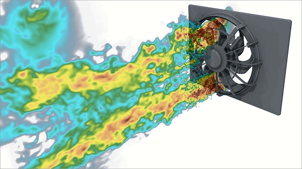
The simulation visualizes how particles are hotter at the time of generation and gradually cools down as they flow with the fluid phase. This analysis provides a holistic overview towards the root problem and goal to be achieved.
Refinement loop
Insights to Market Launch
This section outlines the finalization processes following usability testing, aimed at iterative improvements for a successful market launch. Below are brief illustrations of related experiences.
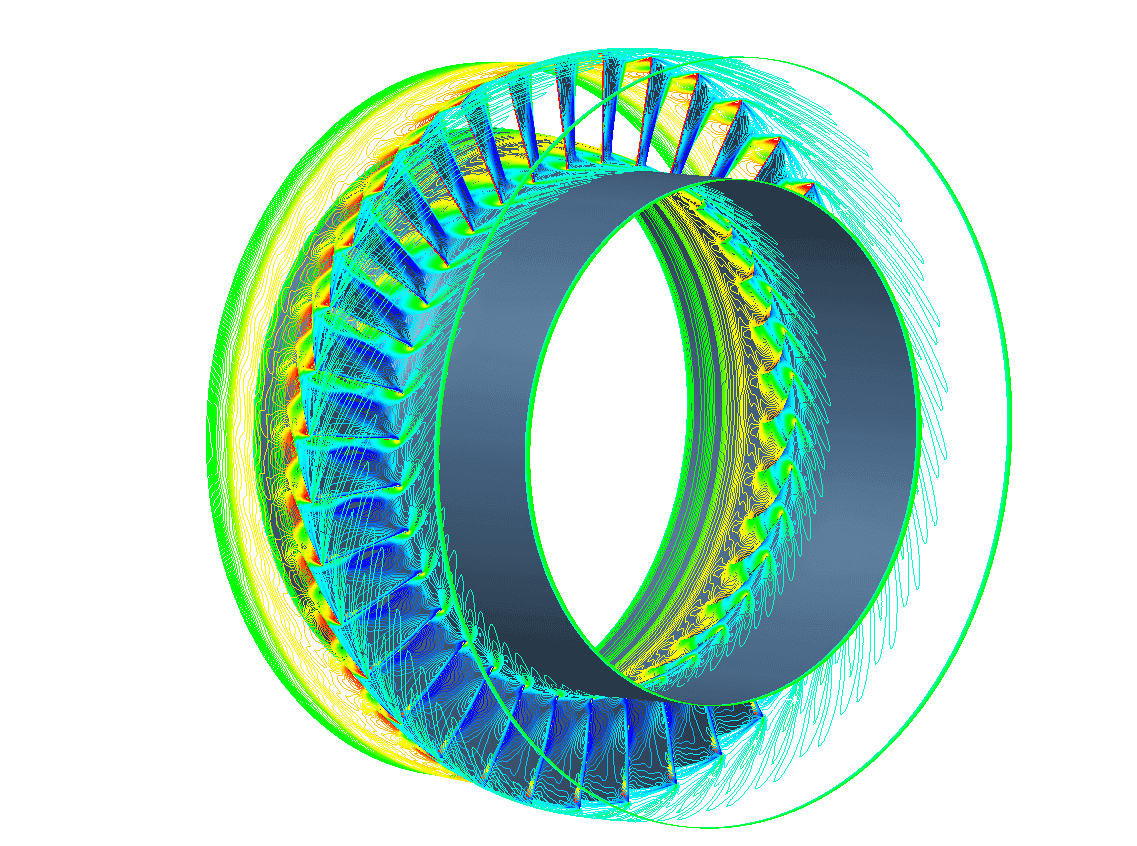
Simulation analytics
Referencing the results section of the design phase, a spectrum of data could be depicted. Below are further illustrations of simulation post-processing visualizations that can be extracted for analysis.
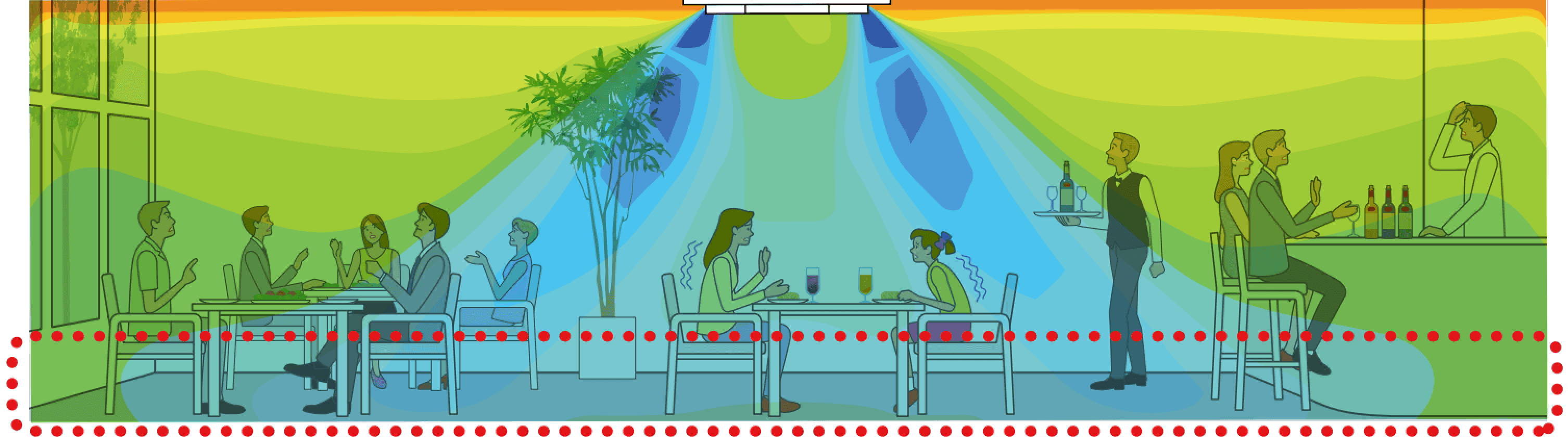

Numerous parameters can be generated to study factors impacting HVAC systems, comparable to heatmaps in UX design. Simulation visualizations reveal how airflow or temperature affects tenant comfort, similar to detecting user behavior trends in UX analytics.
Synthesis workshops:
Design reviews
Themes and insights undergo evaluation against Key Performance Indicators (KPIs) and project requirements established in the initial phase. Collaborative sessions with cross-functional teams occur iteratively to assess feasibility and viability throughout product development phases. Within the simulation team, this occurs for the IT-infrastructure projects too.
Upon confirmation of hypotheses, findings, and results, a more holistic review called “Design Review (DR)” is conducted periodically, typically occurring every few months. Multiple DRs take place across the product development cycle, involving all departments to showcase work status and results. Business and technical evaluations are critiqued by leaders and experts to ensure requirements and quality standards are met.
DESIGN REVIEW 2
Working prototype
Test standard compliant
Delivery schedule
DESIGN REVIEW 1
Conceptual
Feasibility
Schedule plan
DESIGN REVIEW 3
Verified countermeasures if any
Finalized results
Final mass production
NO. OF TASKS / ISSUES /
RECOVERY COST
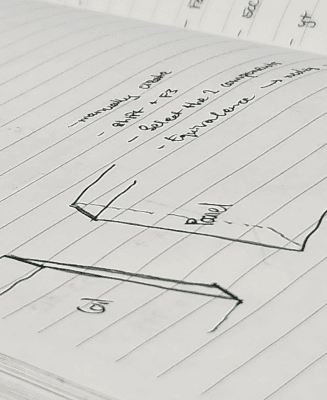
With DRs in place, progress and results are meticulously reviewed to identify necessary changes early in the development cycle. Each iteration considers both technical aspects (system, design, hardware) and user needs (market and business requirements).
The cycle ends with a final DR, where the outcome and potential future work are assessed. A panel of professional stakeholders then issues a "GO" or "NO GO" verdict, guiding the next phase of development.
Takeaways
Building the foundation:
Scalable infrastructure for simulation success
At the core of effective simulations lie the need for scalable and reliable IT infrastructure. From robust storage systems to powerful High Performance Computing (HPC) servers incorporating fast interconnectivity, sizable cores, redundancy and efficient queue management, every element plays a crucial role in ensuring simulations run smoothly and seamlessly. Just as a sturdy foundation is essential for a skyscraper to rise tall, an optimized and load balanced infrastructure is paramount for simulations to scale and deliver accurate results.
Data structure:
The backbone of smart simulation integration
In addition to infrastructure, a structured data type is vital for simulation success. Given the proprietary nature of simulation models and the diverse datasets they involve, the importance of a standardized data structure becomes apparent. It is crucial for data collection to be systematically available, rather than a concoction of manual records or highly unstructured data requiring transformation. Automated recording and logging mechanisms would streamline data management, enabling future analysis and integration with AI capabilities. Just as a well-organized library facilitates easy access to knowledge, the availability or readily accessible or transformed structured data empowers simulations to drive research and extract actionable insights.
Measuring success
A feedback loop for innovation. The role highlights the importance of collaboration and grasping the big-picture via continuous conversations between simulations, other engineering domains and end-users. It is a cycle of iterative feedback and improvement.
For optimal design outcomes, simulation acts as a powerful analysis tool. However, its effectiveness thrives on a two-way street information with other engineering disciplines.
“
”